Dependence Graphs in LLVM
Introduction
Dependence graphs are useful tools in compilers for analyzing relationships between various program elements to help guide optimizations. The ideas behind these graphs are described in papers [1] and [2].
The implementation of these ideas in LLVM may be slightly different than what is mentioned in the papers. These differences are documented in the implementation details.
Data Dependence Graph
In its simplest form the Data Dependence Graph (or DDG) represents data dependencies between individual instructions. Each node in such a graph represents a single instruction and is referred to as an “atomic” node. It is also possible to combine some atomic nodes that have a simple def-use dependency between them into larger nodes that contain multiple- instructions.
As described in [1] the DDG uses graph abstraction to group nodes that are part of a strongly connected component of the graph into special nodes called pi-blocks. pi-blocks represent cycles of data dependency that prevent reordering transformations. Since any strongly connected component of the graph is a maximal subgraph of all the nodes that form a cycle, pi-blocks are at most one level deep. In other words, no pi-blocks are nested inside another pi-block, resulting in a hierarchical representation that is at most one level deep.
For example, consider the following:
for (int i = 1; i < n; i++) {
  b[i] = c[i] + b[i-1];
}
This code contains a statement that has a loop carried dependence on itself creating a cycle in the DDG. The figure bellow illustrates how the cycle of dependency is carried through multiple def-use relations and a memory access dependency.
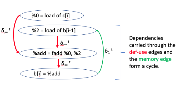
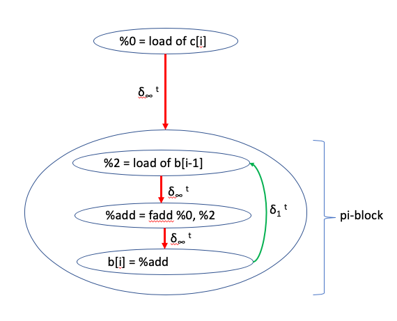
The DDG corresponding to this example would have a pi-block that contains all the nodes participating in the cycle, as shown bellow:
Program Dependence Graph
The Program Dependence Graph (or PDG) has a similar structure as the DDG, but it is capable of representing both data dependencies and control-flow dependencies between program elements such as instructions, groups of instructions, basic blocks or groups of basic blocks.
High-Level Design
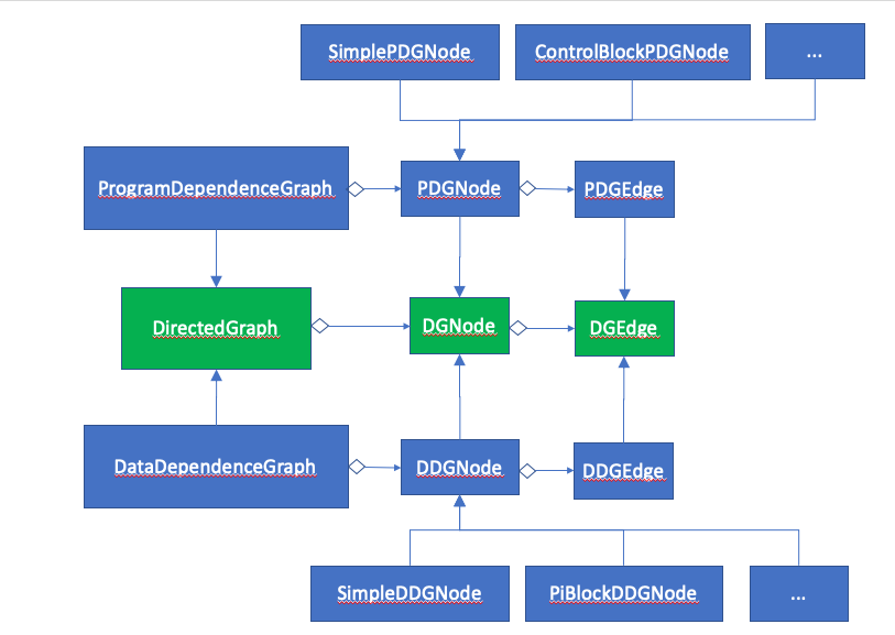
The DDG and the PDG are both directed graphs and they extend the
DirectedGraph class. Each implementation extends its corresponding
node and edge types resulting in the inheritance relationship depicted
in the UML diagram bellow:
Graph Construction
The graph build algorithm considers dependencies between elements of a given set of instructions or basic blocks. Any dependencies coming into or going out of instructions that do not belong to that range are ignored. The steps in the build algorithm for the DDG are very similar to the steps in the build algorithm for the PDG. As such, one of the design goals is to reuse the build algorithm code to allow creation of both DDG and PDG representations while allowing the two implementations to define their own distinct and independent node and edge types. This is achieved by using the well-known builder design pattern to isolate the construction of the dependence graph from its concrete representation.
The following UML diagram depicts the overall structure of the design pattern as it applies to the dependence graph implementation.
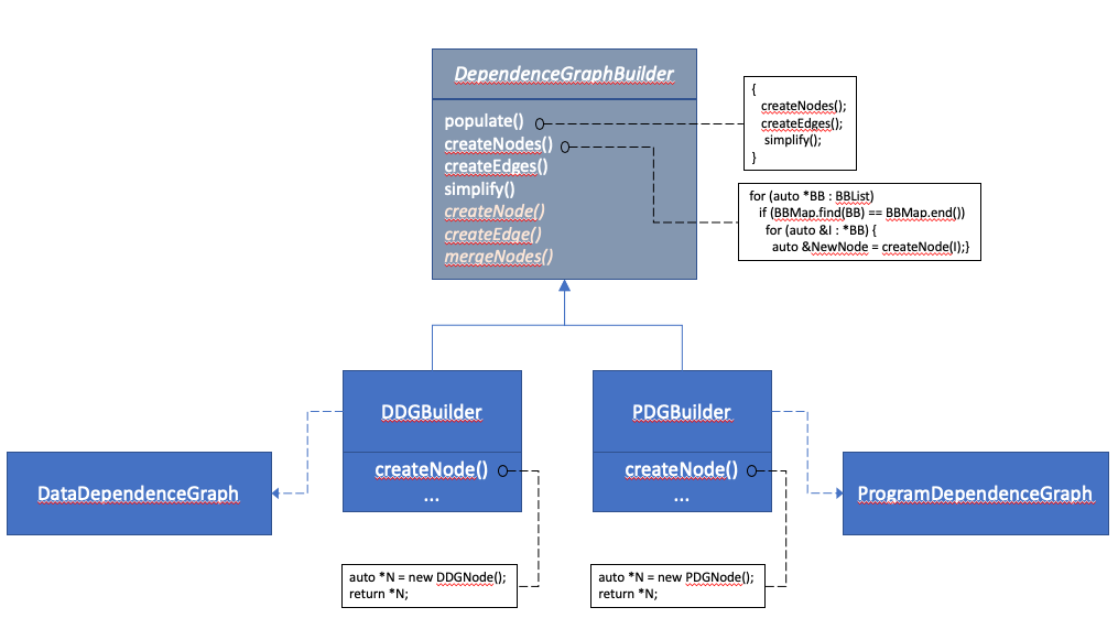
Notice that the common code for building the two types of graphs are
provided in the DependenceGraphBuilder class, while the DDGBuilder
and PDGBuilder control some aspects of how the graph is constructed
by the way of overriding virtual methods defined in DependenceGraphBuilder.
Note also that the steps and the names used in this diagram are for illustrative purposes and may be different from those in the actual implementation.
Design Trade-offs
Advantages:
- Builder allows graph construction code to be reused for DDG and PDG.
- Builder allows us to create DDG and PDG as separate graphs.
- DDG nodes and edges are completely disjoint from PDG nodes and edges allowing them to change easily and independently.
Disadvantages:
- Builder may be perceived as over-engineering at first.
- There are some similarities between DDG nodes and edges compared to PDG nodes and edges, but there is little reuse of the class definitions.
- This is tolerable given that the node and edge types are fairly simple and there is little code reuse opportunity anyway.
Implementation Details
The current implementation of DDG differs slightly from the dependence graph described in [1] in the following ways:
- The graph nodes in the paper represent three main program components, namely assignment statements, for loop headers and while loop headers. In this implementation, DDG nodes naturally represent LLVM IR instructions. An assignment statement in this implementation typically involves a node representing the
storeinstruction along with a number of individual nodes computing the right-hand-side of the assignment that connect to thestorenode via a def-use edge. The loop header instructions are not represented as special nodes in this implementation because they have limited uses and can be easily identified, for example, throughLoopAnalysis.- The paper describes five types of dependency edges between nodes namely loop dependency, flow-, anti-, output-, and input- dependencies. In this implementation memory edges represent the flow-, anti-, output-, and input- dependencies. However, loop dependencies are not made explicit, because they mainly represent association between a loop structure and the program elements inside the loop and this association is fairly obvious in LLVM IR itself.
- The paper describes two types of pi-blocks; recurrences whose bodies are SCCs and IN nodes whose bodies are not part of any SCC. In this impelmentation, pi-blocks are only created for recurrences. IN nodes remain as simple DDG nodes in the graph.
References
| [1] | (1, 2, 3) “D. J. Kuck, R. H. Kuhn, D. A. Padua, B. Leasure, and M. Wolfe (1981). DEPENDENCE GRAPHS AND COMPILER OPTIMIZATIONS.” |
| [2] | “J. FERRANTE (IBM), K. J. OTTENSTEIN (Michigan Technological University) and JOE D. WARREN (Rice University), 1987. The Program Dependence Graph and Its Use in Optimization.” |